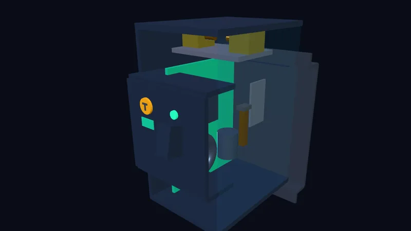
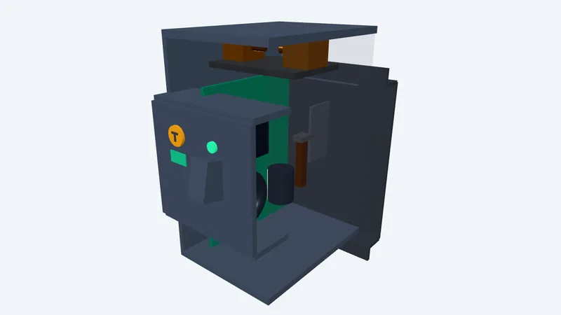
▸ Explore how an AFDD analyzes microsecond current waveforms, zero-crossing flat spots, and RF bursts.
This model visualises product performance testing under BS EN 62606: series micro-gap arc fault ignition, Townsend avalanche ionization, and Cassie-Mayr zero-crossing flat spots distinguishing genuine cable damage from benign drill commutator sparks (mandated under BS 7671 Reg 421.1.7).
Interactive Simulation & Controls:- Simulate loose terminal series arcs and observe Mayr zero-crossing flat spots.
- Adjust DSP detection thresholds and trigger high-frequency 10-50MHz RF noise bursts.
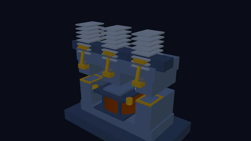
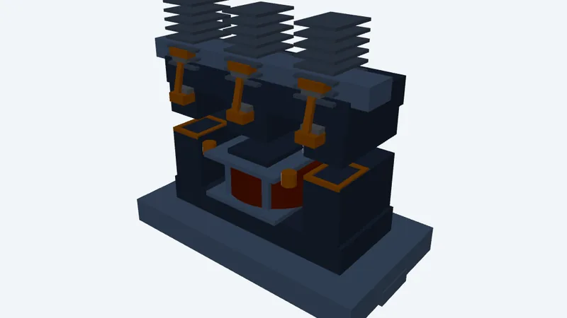
▸ Watch contact bounce micro-arcs erode silver contact tips and see de-ion arc chutes quench plasma.
This cutaway model visualises electromechanical contactor kinematics under BS EN 60947-4-1 (AC-3/AC-4 duty): solenoid pull-in, mechanical contact bounce chatter (<3ms), inductive L di/dt back-EMF kickback, and Lorentz force de-ion arc splitting.
Interactive Simulation & Controls:- Observe contact bounce chatter (1-3ms) during motor start inrush and analyze contact tip wear.
- Toggle RC snubbers and MOV varistors to clamp 2,500V inductive kickback spikes.
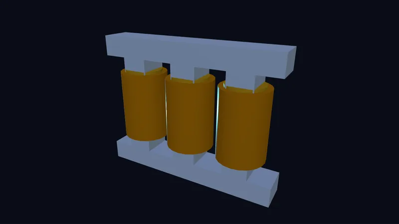
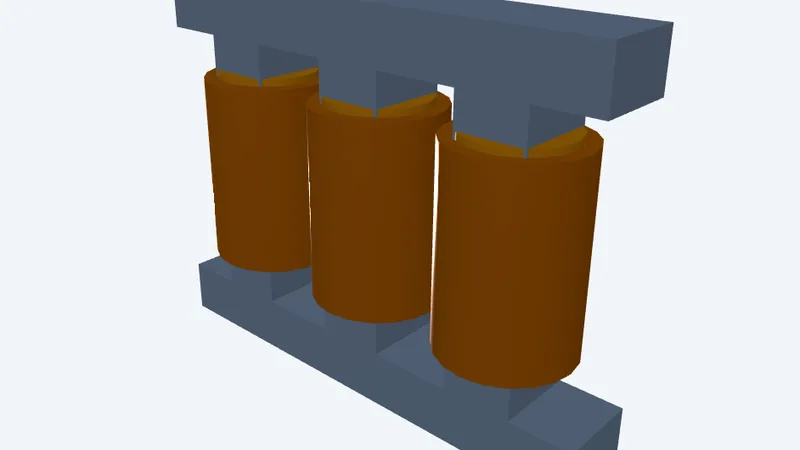
▸ See Dyn11 primary delta and secondary star windings create a 30° phase shift and trap 3rd harmonics.
This 3D model visualises dynamic rotating magnetic flux across a 3-limb laminated core, clock-face vector group phase displacements (Dyn11 11 o'clock 30° lag), and closed-mesh circulating zero-sequence triplen harmonics.
Interactive Simulation & Controls:- Inspect synchronous 50Hz rotating primary vs secondary voltage phasors on an interactive clock dial.
- Unbalance secondary single-phase loads and observe circulating 3rd harmonic currents in the delta mesh.
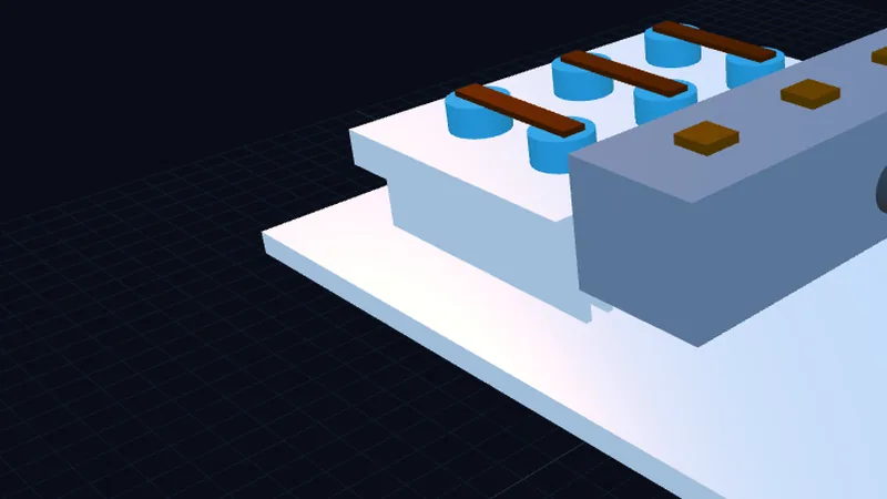
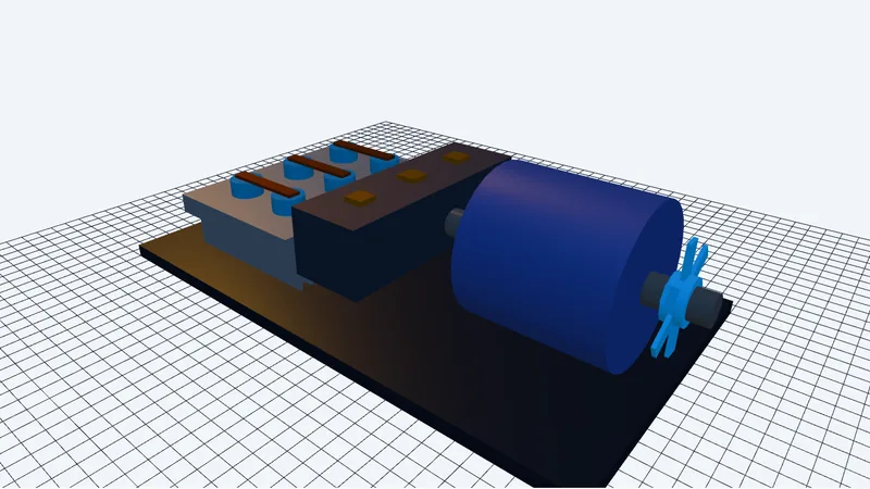
▸ Watch six thyristors chop sine waves to ramp motor voltage and tame starting current spikes.
This model visualises how phase-angle gate triggering smoothly ramps 3-phase stator voltage to prevent mechanical strain and grid voltage dips. As firing angle alpha delays conduction, real-time wave-chopping reduces starting torque and inrush current before switching to mains bypass.
Interactive Simulation & Controls:- Adjust the firing angle from 0° to 180° to see live sine-chopping and motor torque changes.
- Simulate pedestal breakaway voltage boost and observe automatic transition to mains bypass contactors.

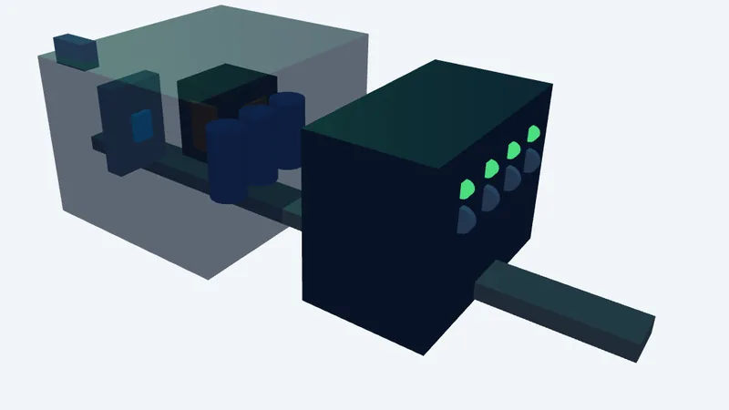
▸ See high-frequency MOSFET switching transform 230V AC into isolated 24V DC power.
This model visualises 100kHz pulse chopping through a compact ferrite core alongside fast-acting 24V electronic circuit breakers. It demonstrates why thermal MCBs fail to trip on 24V control loops while active electronic fuses isolate shorted sensor cables in milliseconds.
Interactive Simulation & Controls:- Trigger 24V cable short-circuits to contrast thermal MCB bus blackouts against selective electronic fuse trips.
- Toggle between SELV and PELV earthing configurations to observe fault current flow paths.
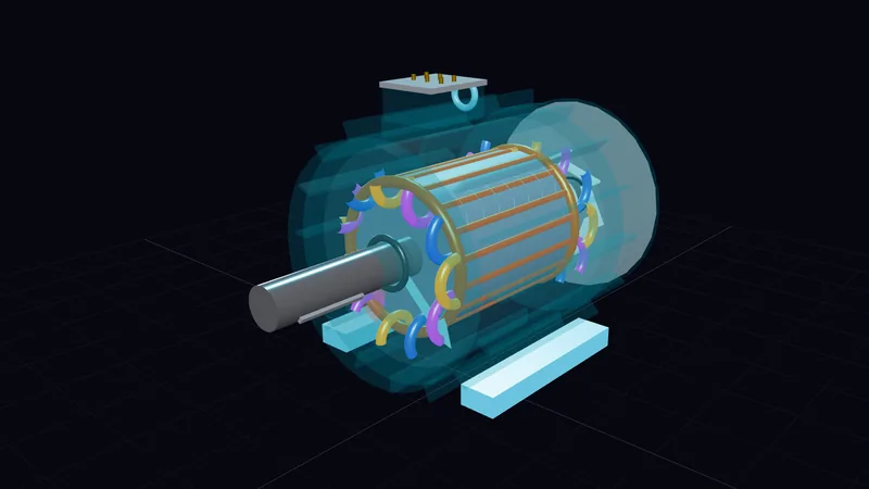
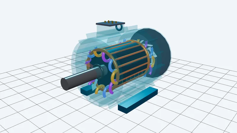
▸ See three AC phase currents generate a smooth rotating magnetic field dragging the rotor.
This 3D model visualises how stationary stator windings create a rotating magnetic flux vector that induces current inside aluminium rotor bars. It shows how mechanical slip produces shaft torque and how star-delta links reconfigure terminal voltage.
Interactive Simulation & Controls:- Explode the 3D motor assembly to inspect stator slots, cage bars, and terminal box links.
- Vary shaft load and grid frequency to watch real-time slip lag and rotor current glow.
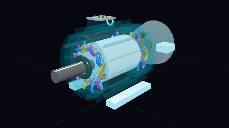
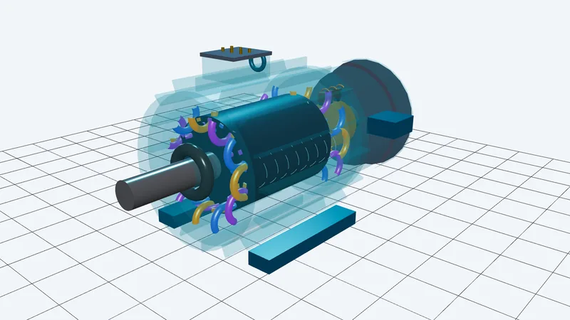
▸ Follow resistance through spinning brass slip rings as peak torque shifts to zero RPM.
This model visualises a wound rotor motor with brass slip rings, graphite brushes, and a four-step external starting rheostat. It demonstrates how adding rotor resistance alters the torque-speed curve to launch heavy inertia loads without high current spikes.
Interactive Simulation & Controls:- Operate the 4-step rheostat lever to see peak torque shift to zero RPM on the dynamic curve.
- Explode the brush-gear assembly to inspect carbon brush holders, slip rings, and rotor coils.
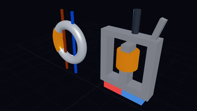
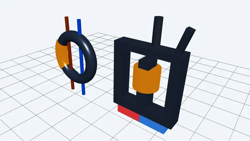
▸ Watch residual earth fault current unbalance magnetic flux in a toroid to trip the relay.
This cutaway model visualises how a core balance CT senses milliamps of leakage current between line and neutral conductors. It demonstrates how opposing magnetic flux releases a spring-loaded relay armature to snap contacts open in milliseconds.
Interactive Simulation & Controls:- Inject 30mA earth leakage or DC blinding currents to observe core flux and relay unlatching.
- Run virtual multi-function tester trip tests (0.5x, 1x, 5x, Auto-Ramp) on the live bench.

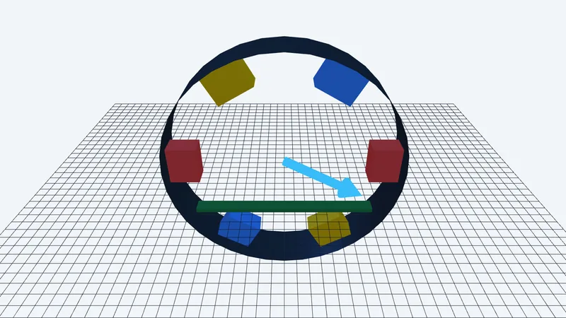
▸ Observe three 120-degree phases deliver constant instantaneous power while neutral current cancels to zero.
This model visualises why 3-phase power delivers smooth constant instantaneous power while cancelling neutral return current on balanced loads. It demonstrates instantaneous power summing and reveals how non-linear 3rd-harmonic currents stack up inside neutral conductors.
Interactive Simulation & Controls:- Unbalance phase loads to observe tip-to-tail vector summation and neutral return current flow.
- Add 3rd harmonic distortion to see triplen currents accumulate in the neutral conductor.
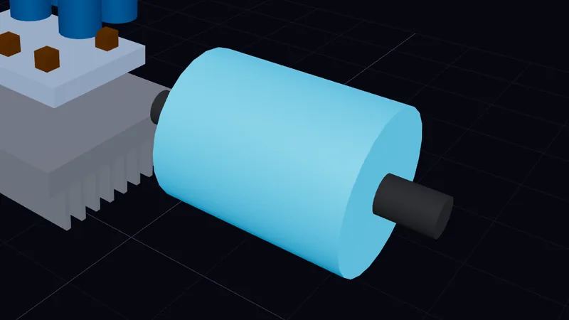
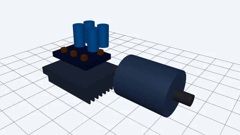
▸ Watch six IGBT switches pulse DC voltage to synthesize variable-frequency AC motor power.
This model visualises SPWM pulse slicing across a 3-phase IGBT inverter bridge driving an induction motor. It shows scalar V/f voltage boosting at low speeds and high dV/dt voltage reflection spikes on long motor cables.
Interactive Simulation & Controls:- Adjust carrier frequency and fundamental speed to observe PWM pulse slicing and motor rotation.
- Increase motor cable length to simulate dV/dt voltage reflection spikes at motor terminals.

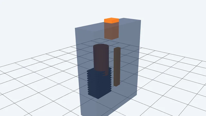
▸ See a bimetal strip flex under overload while a solenoid plunger snaps short circuits open.
This cutaway model visualises the dual tripping mechanisms inside a miniature circuit breaker alongside an 11-blade de-ion arc chute. It contrasts slow thermal bimetal bending against millisecond magnetic plunger strikes across Type B, C, and D curves.
Interactive Simulation & Controls:- Adjust current multipliers to watch thermal bimetal flex versus instant magnetic solenoid tripping.
- Toggle Type B, C, and D log-log time-current curves to verify disconnect times against prospective fault currents.
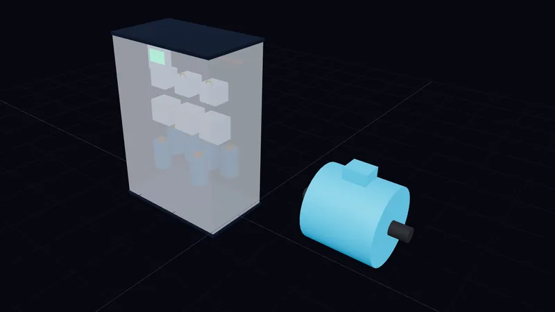
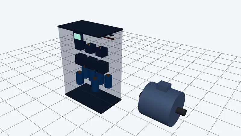
▸ Trace capacitor banks supplying reactive current locally to shrink the power triangle and current draw.
This model visualises the relationship between active, reactive, and apparent power alongside time-domain energy flow. It shows how inductive loads draw lagging current and demonstrates how automatic capacitor switching corrects power factor to reduce supply kVA.
Interactive Simulation & Controls:- Adjust active power and power factor sliders to watch the phasor triangle expand and contract.
- Switch detuned capacitor banks in and out to observe power factor correction and harmonic resonance.
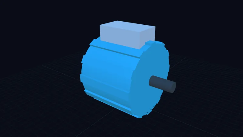
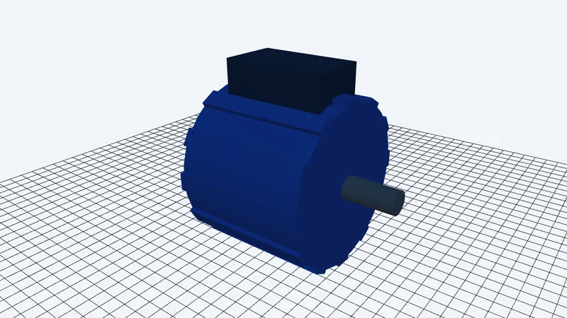
▸ Watch starting capacitors synthesize a rotating field until a centrifugal switch snaps open.
This model visualises why single-phase motors lack starting torque until an auxiliary winding and capacitor synthesize a 90° phase shift. It demonstrates Double Revolving Field Theory and shows centrifugal switch contacts opening as the rotor reaches 75% operating speed.
Interactive Simulation & Controls:- Switch between Split-Phase, CSIR, PSC, and CSCR topologies to inspect winding phase shifts.
- Accelerate the motor to watch centrifugal flyweights expand and snap the starting switch open at 75% speed.
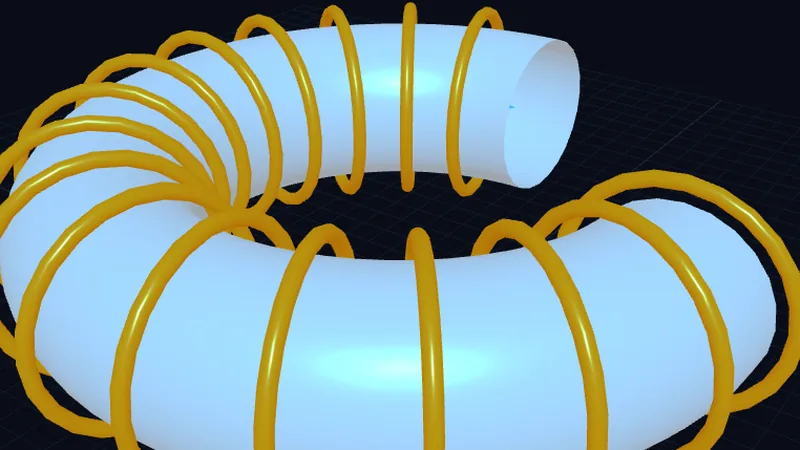
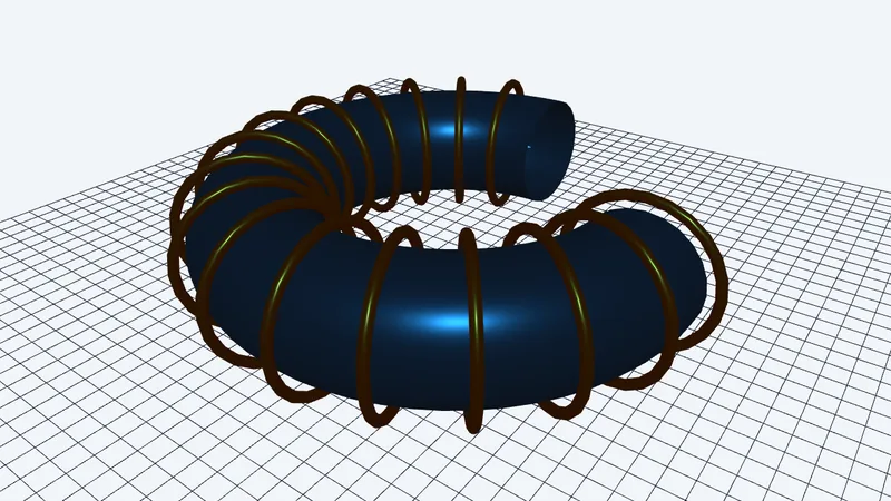
▸ Watch microscopic magnetic domains align as excitation current traces out a core hysteresis loop.
This model visualises Weiss domain rotation, magnetic saturation, remanent flux, and coercive force inside transformer steel. It shows how laminating core steel breaks up circulating eddy current loops to reduce iron losses.
Interactive Simulation & Controls:- Select between CRGO steel, Mumetal, ferrite, and mild steel to compare hysteresis loop shapes.
- Adjust core lamination thickness to see circulating eddy current loops shrink and iron losses drop.
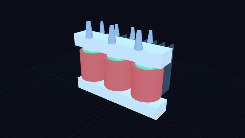
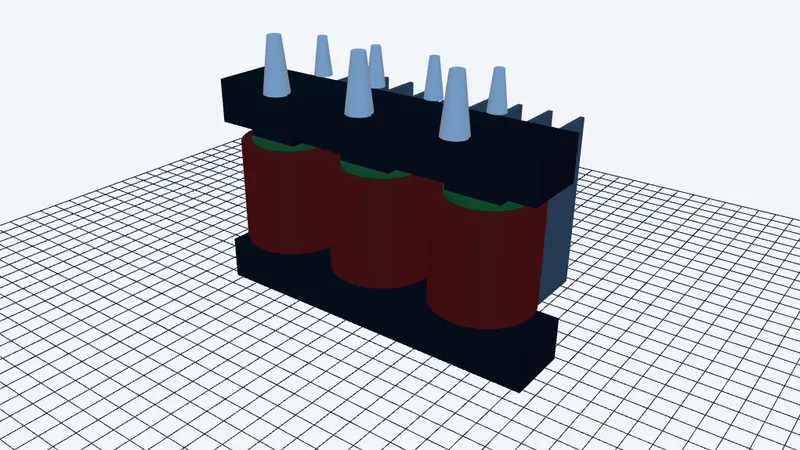
▸ Watch alternating core flux step voltage up or down while copper and iron losses vary.
This model visualises Faraday’s mutual induction across primary and secondary windings in a 3-phase distribution transformer. It demonstrates voltage regulation under lagging loads and highlights the operating point where fixed iron losses equal variable copper losses for peak efficiency.
Interactive Simulation & Controls:- Change load percentage and power factor to find the peak efficiency point where iron and copper losses equal.
- Adjust off-circuit tap changer positions and inspect Dyn11 vector group clock-face phase shifts.